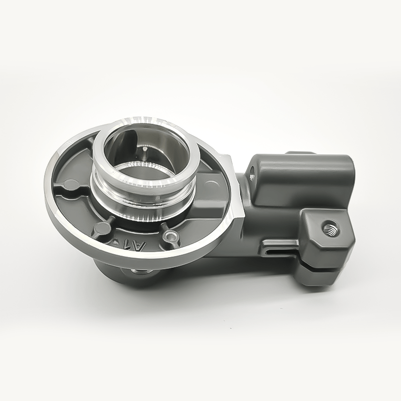
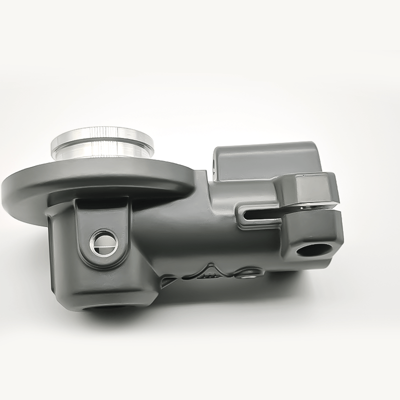
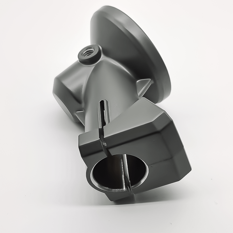
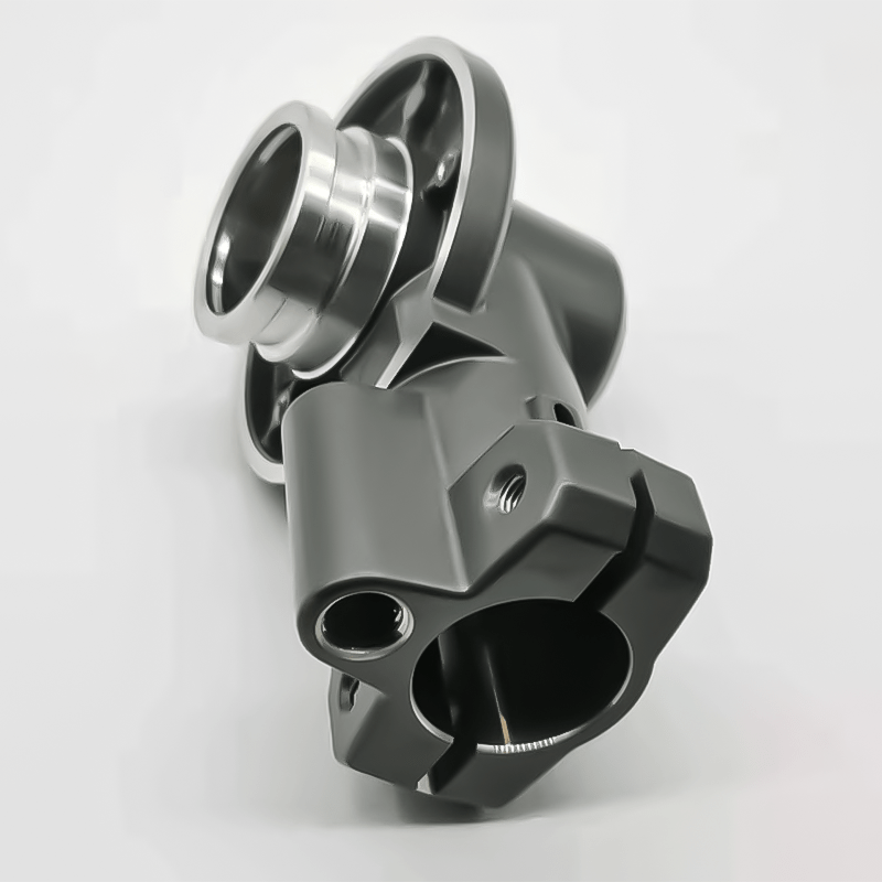
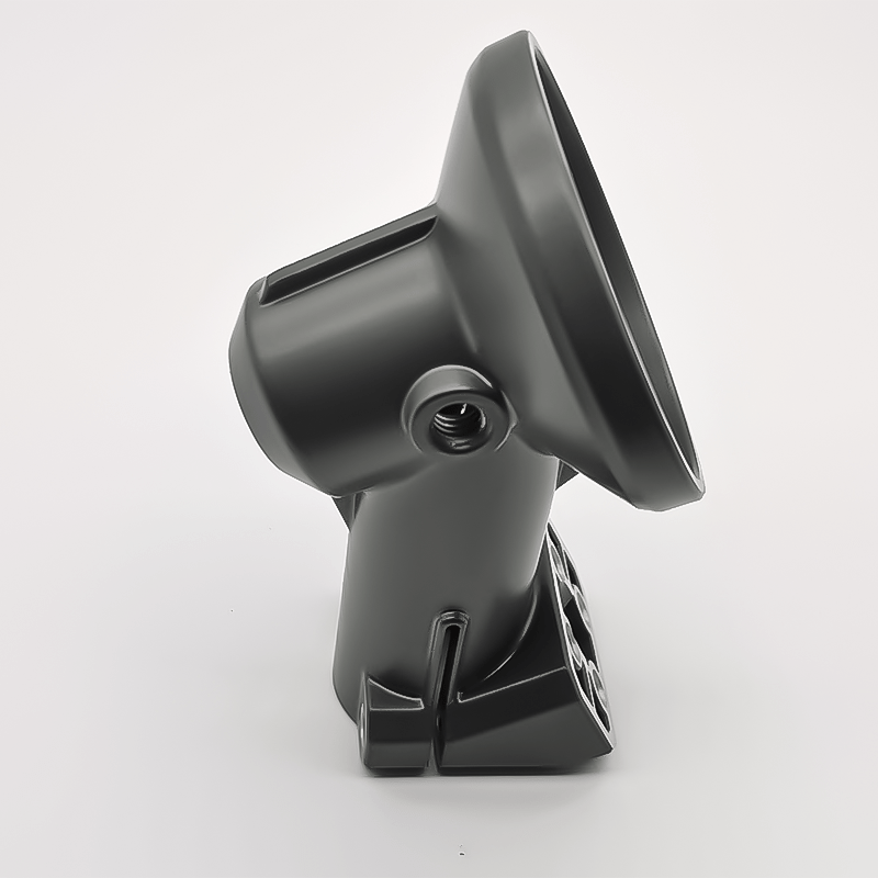
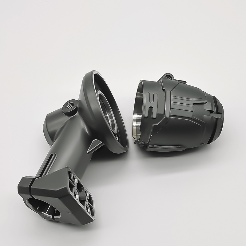
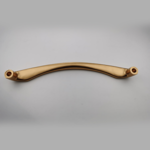
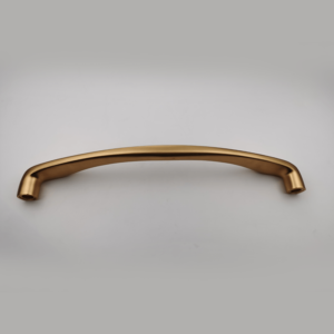
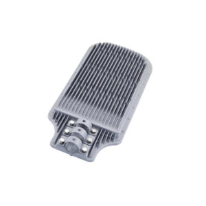
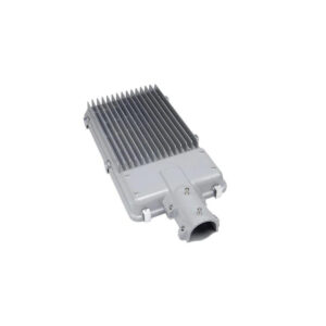
Electronic Plated Aluminum Alloy Die Casting for Camera Bracket
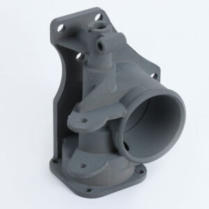
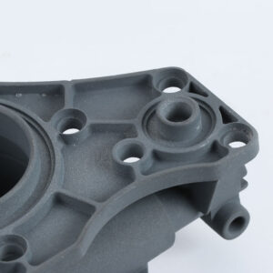
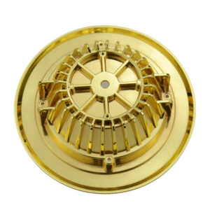
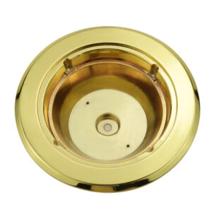
This camera bracket housing is made from ADC12, which is a typically aluminum alloy die-casting with electronic plated. The surface finishing process contains batching, machining, oxidation. The number of parting surfaces of die casting mold is multiple parting surfaces. The die-casting mold cavity number is multi-cavity mold. The die-casting mold installation method: semi-fixed die-casting mold. The main processing equipment contains: die-casting machine, punching machine, CNC polishing machine, drilling machine, tapping machine. The process flow: die casting → punching → rolling grinding → batching → lathe → oxidation → salt spray test → full inspection. Our quality standard is based on ISO900, the inspection frequency: AQL=0.56. The tolerance is ±0.01 mm. Die casting height: 8mm, Die casting length: 37mm, Die casting width: 9mm, Die casting weight: 63g.
- Material Selection
- Design Geometry
- Advantages of Die Casting
- Material and Hardness
- Temperatures and Life
- Inquiry
Material Selection
The main die casting alloys are: aluminium, zinc, magnesium, copper, lead, and tin; although uncommon, ferrous die casting is also possible. Specific die casting alloys include: zinc aluminium; aluminium to, e.g. The Aluminum Association standards: AA 380, AA 384, AA 386, AA 390; and AZ91D magnesium. The following is a summary of the advantages of each alloy:
1. Aluminium: lightweight; high dimensional stability for very complex shapes and thin walls; good corrosion resistance; good mechanical properties; high thermal and electrical conductivity; retains strength at high temperatures.
2. Zinc: the easiest metal to cast; high ductility; high impact strength; easily plated; economical for small parts; promotes long die life.
3. Magnesium: the easiest metal to machine; excellent strength-to-weight ratio; lightest alloy commonly die cast.
4. Copper: high hardness; high corrosion resistance; highest mechanical properties of alloys die cast; excellent wear resistance; excellent dimensional stability; strength approaching that of steel parts.
5. Silicon tombac: high-strength alloy made of copper, zinc and silicon. Often used as an alternative for investment cast steel parts.
6. Lead and tin: high density; extremely close dimensional accuracy; used for special forms of corrosion resistance.
As of 2008, maximum weight limits for aluminium, brass, magnesium, and zinc castings are estimated at approximately 70 pounds (32 kg), 10 lb (4.5 kg), 44 lb (20 kg), and 75 lb (34 kg), respectively. By late-2019, press machines capable of die casting single pieces over-100 kilograms (220 lb) were being used to produce aluminium chassis components for cars.
Material Selection
| Metal | Minimum section | Minimum draft |
| Aluminium alloys | 0.89 mm (0.035 in) | 1:100 (0.6°) |
| Zinc alloys | 0.63 mm (0.025 in) | 1:200 (0.3°) |
| Brass and bronze | 1.27 mm (0.050 in) | 1:80 (0.7°) |
| Magnesium alloys | 1.27 mm (0.050 in) | 1:100 (0.6°) |
Design Geometry
1. Draft is the amount of slope or taper given to cores or other parts of the die cavity to allow for easy ejection of the casting from the die. All die cast surfaces that are parallel to the opening direction of the die require draft for the proper ejection of the casting from the die.[12] Die castings that feature proper draft are easier to remove from the die and result in high-quality surfaces and more precise finished product.
2. Fillet is the curved juncture of two surfaces that would have otherwise met at a sharp corner or edge. Simply, fillets can be added to a die casting to remove undesirable edges and corners.
3. Parting line represents the point at which two different sides of a mould come together. The location of the parting line defines which side of the die is the cover and which is the ejector.[13]
4. Bosses are added to die castings to serve as stand-offs and mounting points for parts that will need to be mounted. For maximum integrity and strength of the die casting, bosses must have universal wall thickness.
5. Ribs are added to a die casting to provide added support for designs that require maximum strength without increased wall thickness.
6. Holes and windows require special consideration when die casting because the perimeters of these features will grip to the die steel during solidification. To counteract this effect, generous draft should be added to hole and window features.
Advantages of Die Casting
1. Excellent dimensional accuracy (dependent on casting material, but typically 0.1 mm for the first 2.5 cm (0.004 inch for the first inch) and 0.02 mm for each additional centimeter (0.002 inch for each additional inch).
2. Smooth cast surfaces (Ra 1–2.5 micrometres or 0.04–0.10 thou rms).
3. Thinner walls can be cast as compared to sand and permanent mould casting (approximately 0.75 mm or 0.030 in).
4. Inserts can be cast-in (such as threaded inserts, heating elements, and high strength bearing surfaces).
5. Reduces or eliminates secondary machining operations.
6. Rapid production rates.
7. Casting tensile strength as high as 415 megapascals (60 ksi).
8. Die casting fluid length is unaffected by solidification range, unlike permanent molds, sand castings, and other types.
9. Corrosion rates for die castings are slower than those for sand castings due to the smoother surface of the die castings.
Material and Hardness
Die and component material and hardness for various cast metals
| Die component | Cast metal | |||||
| Tin, lead & zinc | Aluminium & magnesium | Copper & brass | ||||
| Material | Hardness | Material | Hardness | Material | Hardness | |
| Cavity inserts | P20 | 290–330 HB | H13 | 42–48 HRC | DIN 1.2367 | 38–44 HRC |
| H11 | 46–50 HRC | H11 | 42–48 HRC | H20, H21, H22 | 44–48 HRC | |
| H13 | 46–50 HRC | |||||
| Cores | H13 | 46–52 HRC | H13 | 44–48 HRC | DIN 1.2367 | 40–46 HRC |
| DIN 1.2367 | 42–48 HRC | |||||
| Core pins | H13 | 48–52 HRC | DIN 1.2367 prehard | 37–40 HRC | DIN 1.2367 prehard | 37–40 HRC |
| Sprue parts | H13 | 48–52 HRC | H13 DIN 1.2367 | 46–48 HRC 44–46 HRC | DIN 1.2367 | 42–46 HRC |
| Nozzle | 420 | 40–44 HRC | H13 | 42–48 HRC | DIN 1.2367 H13 | 40–44 HRC 42–48 HRC |
| Ejector pins | H13 | 46–50 HRC | H13 DIN 1.2367 | 42–48 HRC 42–48 HRC | DIN 1.2367 H13 | 40–44 HRC 42–48 HRC |
| Plunger shot sleeve | H13 | 46–50 HRC | H13 DIN 1.2367 | 42–48 HRC 42–48 HRC | DIN 1.2367 H13 | 42–46 HRC 42–46 HRC |
| Holder block | 4140 prehard | ~300 HB | 4140 prehard | ~300 HB | 4140 prehard | ~300 HB |
Temperatures and Life
Typical die temperatures and life for various cast materials
| Zinc | Aluminium | Magnesium | Brass (leaded yellow) | |
| Maximum die life [number of cycles] | 1,000,000 | 100,000 | 100,000 | 10,000 |
| Die temperature [C° (F°)] | 218 (425) | 288 (550) | 260 (500) | 500 (950) |
| Casting temperature [C° (F°)] | 400 (760) | 660 (1220) | 760 (1400) | 1090 (2000) |

